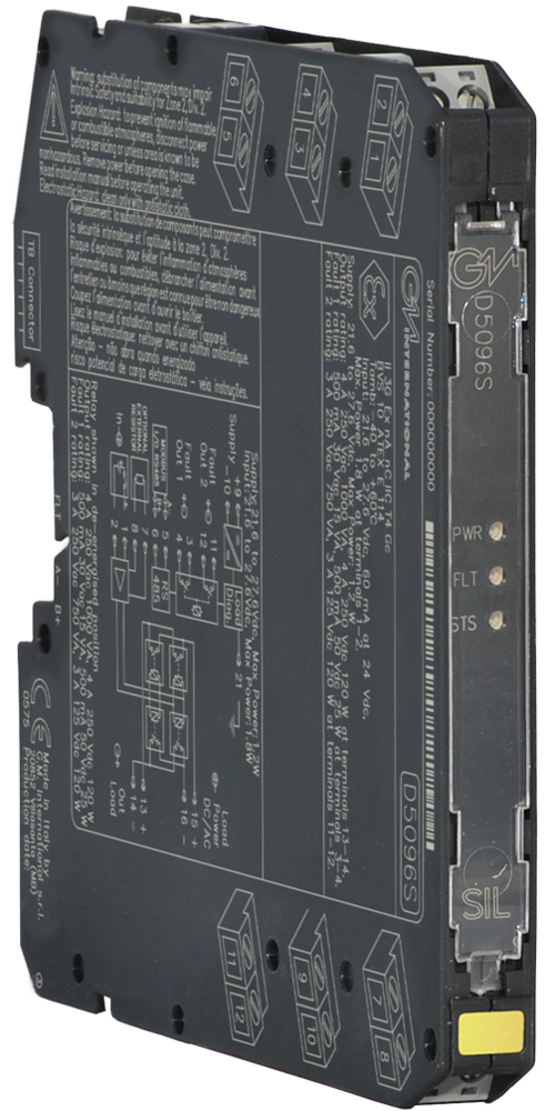
رله مدل D5096S برند GMI – ماژول خروجی رله SIL 3

ماژول D5096 یک ماژول رله است که برای سوئیچینگ (قطع و وصل) مدارهای مرتبط با ایمنی در صنایع پرخطر طراحی شده و تا سطح SIL 3 قابل استفاده است.

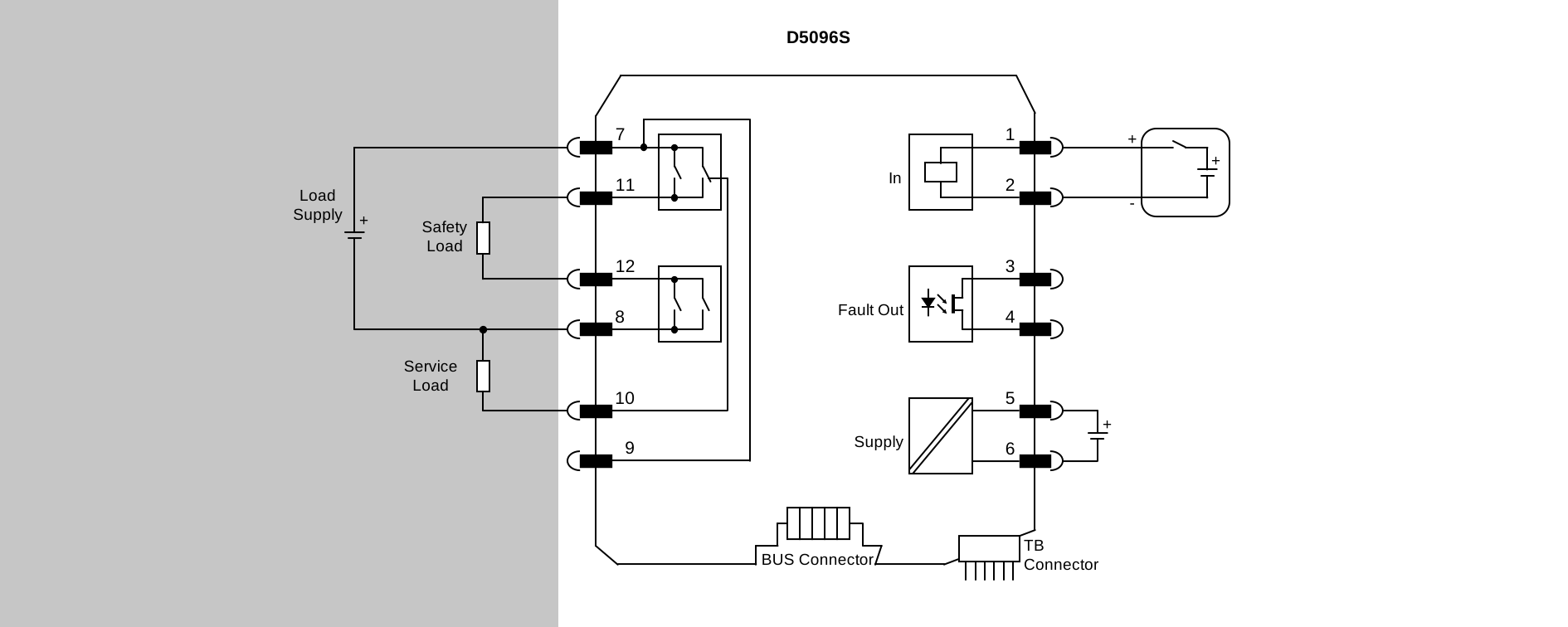
این ماژول بین ورودی و کنتاکت‌های خروجی ایزولاسیون الکتریکی ایجاد می‌کند. همچنین دارای ۲+۲ کنتاکت رله Normally Open (NO) است که به صورت موازی و سپس سری به یکدیگر متصل شده‌اند تا از عملکردهای ناخواسته (Spurious Trip) جلوگیری کرده و دسترس‌پذیری فرایند را افزایش دهند.

عملکرد ایمنی SIL 3 با دسترس‌پذیری بالا برای هر دو نوع بار زیر فراهم شده است:

  • Normally Energized (NE): بارهایی که در حالت عادی برقدار هستند.
  • Normally De-energized (ND): بارهایی که در حالت عادی بدون برق هستند.
  • بارهای سیستم‌های Fire & Gas (F&G) نیز پشتیبانی می‌شوند.

این ماژول امکان ایزوله کردن بار از منبع تغذیه در هر دو قطب (مثبت و منفی) را فراهم می‌کند.

سازگاری گسترده‌ای با انواع سیستم‌های DCS و PLC تضمین شده است. همچنین تست پالسی خروجی (Driving Pulse Testing) به کمک یک مدار داخلی اختصاصی امکان‌پذیر است؛ این مدار از چشمک‌زدن LEDها و عملکرد ناپایدار کنتاکت‌های رله هنگام تست جلوگیری می‌کند.

علاوه بر این، ماژول دارای قابلیت‌های پیشرفته تشخیص خطا است و موارد زیر را پایش می‌کند:

  • تشخیص اتصال کوتاه (Short Circuit)
  • تشخیص مدار باز (Open Circuit)
  • پایش ولتاژ بار (Load Voltage Monitoring)

این نظارت‌ها هم در زمانی که بار خاموش (OFF) است و هم زمانی که بار روشن (ON) است انجام می‌شوند.

در صورت بروز خطا در تجهیزات یا سیم‌کشی میدان (Field)، وضعیت خطا به‌طور مستقیم به خروجی دیجیتال PLC (PLC DO) منعکس می‌شود و علاوه بر آن، با باز شدن خروجی خطا (Fault Output) نیز اعلام می‌گردد.

ویژگی‌ها
🔹 ایزولاسیون ورودی/خروجی/منبع تغذیه
🔹 تک کاناله
🔹 قابل نصب در Zone 2
🔹 SIL 3 / SC 3 برای بارهای NE/ND با درایور NE/ND
کانال‌ها
1
وضعیت
فعال

Technical Data

Supply

Type 24 Vdc nom (18 to 30 Vdc), reverse polarity protected.
Current Consumption 15 mA @ 24 Vdc, typical.
Power Dissipation 0.35 W @ 24 Vdc, typical.

Input

Type 24 Vdc nom (21.6 to 27.6 Vdc), reverse polarity protected. Relay coils are internally protected with suppressor diodes.
Current Consumption 45 mA @ 24 Vdc, typical.
Power Dissipation 1.1 W @ 24 Vdc, typical.

Output

Type Voltage free 2+2 SPST relay contact (2 paralleled contacts in series) at terminals 7-11 and 8-12, close when relay energized, open in de-energized condition.
Contact material Ag Alloy (Cd free), gold plated.
Contact rating 5 A 250 Vac 1250 VA, 5 A 250 Vdc 140 W (resistive load).
Contact min. switching current 1 mA.
Contact inrush current 6 A @ 24 Vdc, 250 Vac.
DC and AC load breaking capacity refer to Instruction Manual.
Contact current derating refer to Instruction Manual.
Mechanical / electrical life 5 * 10⁶ / 3 * 10⁴ operation, typical.
Operate / release time 30 ms / 30 ms, typical.

Fault

Type Load & line short/open circuit, supply voltage monitoring.
Line/load off ok 25 Ω ≤ resistance ≤ 19 kΩ, typical.
Line/load off fault resistance ≤ 15 Ω or ≥ 21 kΩ, typical.
Line/load on ok 15 mA rms ≤ current ≤ 5 A rms, typical.
Line/load on fault current ≤ 5 mA rms or ≥ 6 A rms, typical.
Load supply voltage ok ≥ 20 Vdc/Vac, typical.
Load supply voltage fault ≤ 5 Vdc/Vac, typical.
Fault signalling voltage free NE SPST optocoupled open-collector transistor (output de-energized in fault condition).
Fault rating 100 mA @ 35 Vdc.
Fault output voltage drop < 1 V.
Response time 0.5 s, typical.

Isolation

Test Voltage Output/Input 1.5 kV; Output/Supply 1.5 kV; Output/Fault Output 1.5 kV; Input/Supply 500 V; Input/Fault Output 500 V; Supply/Fault Output 500 V.

Environmental conditions

Operating temperature temperature limits –40 to +70 °C.
Storage temperature temperature limits -45 to +80 °C.

Mounting

Type DIN-Rail 35 mm, with or without Power Bus or on custom Term. Board.
Weight about 125 g.
Connection by polarized plug-in disconnect screw terminal blocks to accommodate terminations up to 2.5 mm² (13 AWG).
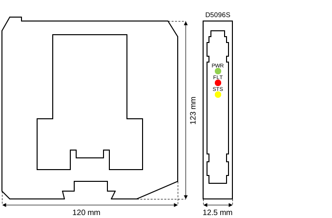
Dimensions Width 12.5 mm, Depth 123 mm, Height 120 mm.

Data Sheet

Datasheet of D5096 ( EN )
D5000 Series Common Specifications and Dimensional Drawing ( EN )

Instruction Manual

Instruction Manual D5096 ( EN | CN )
EAC safety instruction manual for D5000 series ( EN | RU )
Instruction Manual D5000-D5200 Series ( EN )
ATEX safety instruction manual for D5000 series ( EN | IT )
Safety Manual D5096 ( EN )
CCC Ex safety instruction manual for D5000 series ( EN | CN )
Ex safety instruction manual for D5000 series ( RU )
INMETRO safety instruction manual for D5000 series ( PT )

Certifications

Type Description Area Number Issued by Issue Date
ATEX DEKRA ATEX D5000 Relay Series English Certificate ( EN | DE ) Europe BVS 10 ATEX E 114 X DEKRA 2022-04-12
EMC D5000/D6000 EAC EMC Declaration of Conformity ( RU ) Eurasian Community ЕАЭС N RU Д-IT.PA08.B.82326/24 CONTROL 2024-09-26
Ex D5000 CCC certificate for China ( EN ) China 2020322316000978 NEPSI 2025-06-23
Ex PESO Certificate series D5000 ( EN ) India P652307 PESO 2026-01-01
Ex EAC Ex Certificate for D5000 Series (2nd half) ( RU ) Eurasian Community ЕАЭС RU С-IT.AA87.В.01516/25 CCVE 2025-09-30
Ex Emirates Certificate of Conformity D5000 ( EN ) United Arab Emirates 25-06-152424/E25-06-158814/NB0002 SGS 2024-06-05
Ex UL-cUL D5094, D5095, D5096, D5096-100, D5097 Divisions ( EN ) North America 20200226-E22230 UL 2020-02-28
Ex INMETRO Certificate DNV 13.0109 X for D5000 ( PT ) Brazil DNV 13.0109 X DNV 2025-12-10
IECEx DEKRA IECEx for D5000 Series ( EN ) International IECEx BVS 10.0072X DEKRA 2022-04-14
Maritime KR Maritime Certificate D5000 Series ( EN ) International MIL20769-EL002 KR 2024-06-26
Maritime DNV Maritime Certificate TAA00001U0 for D5000 series for website ( EN ) International TAA00001U0 DNV-GL 2024-04-02
SIL TUV IT 25 SIL 0634 SIL Certificate Summary ( EN ) International TUV IT 25 SIL 0634 TUV_SUD 2025-09-19
SIL TUV IT 25 SIL 0636 SIL Certificate Summary ( EN ) International TUV IT 25 SIL 0636 TUV_SUD 2025-09-19

Declarations of Conformity

EU Declaration of Conformity for D5000 relays ( EN | IT )
Declaration of Conformity G3 compliance ( EN )

Dimensions

Image of D5096_size

Drawings

2d_drawing_D5000_dwg ( EN )
3d_drawing_D5000_dwg ( EN )
3d_drawing_D5000_stp ( EN )
محصولات جایگزین